A cloud deployment or a virtual data center has a variety of applications across multiple tenants. These applications and tenants require isolation from each other for security, fault isolation, and avoiding overlapping IP addressing issues. The NSX logical switch creates logical broadcast domains or segments to which an application or tenant virtual machine can be logically wired. The logical switch is nothing but a distributed port group on the distributed switch. The logical switch can expand distributed switches by being associated with a port group in each distributed switch.The NSX controller is the central control point for all logical switches within a network and maintains information of all virtual machines, hosts, NSX logical switches, and VXLANs. A logical switch is mapped to a unique VXLAN, which encapsulates the virtual machine traffic and carries it over the physical IP network.
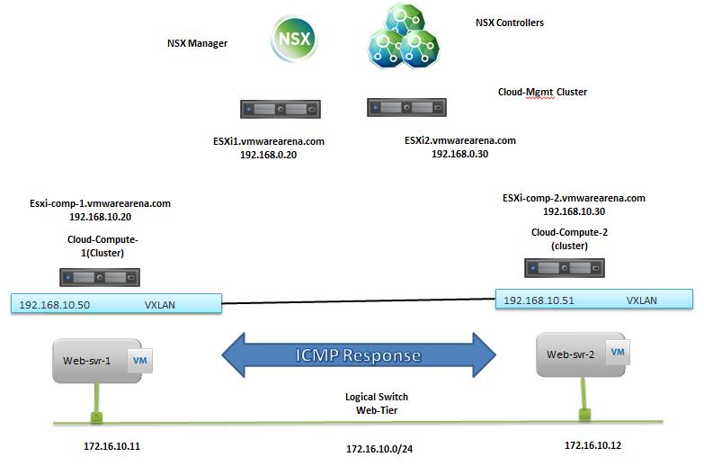
Below is my Lab topology for Logical Switching. I am going to create a Logical switch called “Web-Tier” and attach the 2 Virtual Machines “Web-Svr-1” & “Web-Svr-2” into the created logical switch. This Logical Switch will allow the communication between these 2 Virtual Machines in the different cluster without having actual physical subnet configured at the Physical network layer. For both VM’s, configured IP address is in “172.16.10.x” network and ESXi hosts are on the subnet “192.168.10.x”.
Create NSX Logical Switch:
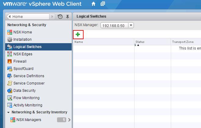
To create the logical Switch , Login to Web Client ->Networking & Security -> Logical Switches -> + symbol to add new logical switch
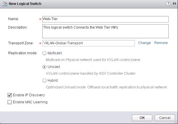
Provide the Name and Description of New NSX Logical Switch. Select the Transport Zone which we have created in the previous step. Select the replication mode as same which you have configured for “VXLAN-Global-Transport” Transport Zone. I have selected “Unicast” mode. Click on Ok to create the new logical switch.
New NSX Logical Switch called “Web-Tier” is created. Which is assigned to VNI number “5000”.
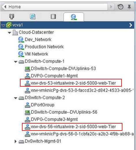
As we discussed earlier, the Logical switch is nothing but a Distributed Port Group in your DvSwitches. When you create a Logical Switch, It will create DvPortgroup in all the associated dvSwitches which are part of the Clusters connected in the Global Transport Zone. So I have created a Logical Switch Called “Web-Tier”. I can see the PortGroups “VXW-dvs-53-virtualwire-2-sid-5000-web-Tier” is created in my both distributed switches.
Associate Virtual Machines to Logical Switch:
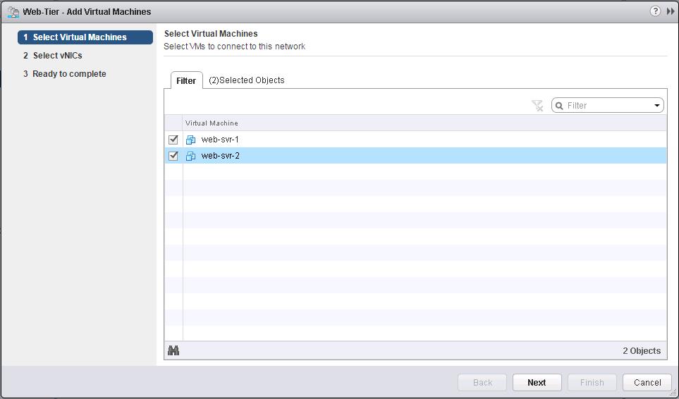
Once Logical switches are created, We need to associate the workloads (Virtual machines) with the logical switch created in the previous steps. Click on VM symbol to associate the virtual machines to this Logical Switch “Web-Tier”
Select the Virtual Machines from the list to associate with this logical switch (Web-Tier). I have associated the above 2 VM’s from different cluster into this logical switch. Click on Next.
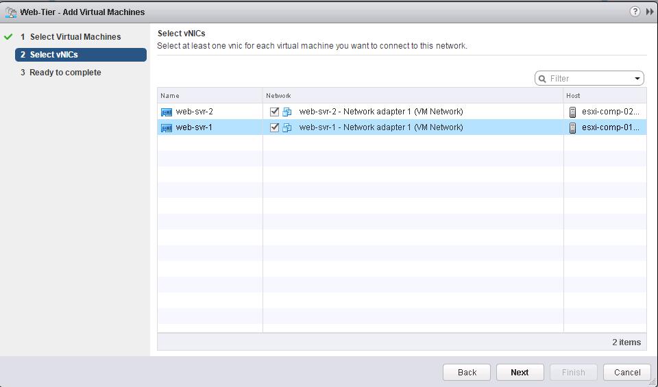
For Multi-Nic VM’s, You can even select the specific vNic to connect to this Logical Switch (Web-Tier). My both VM’s are having only 1 vNic. Select the vNics and Click Next.
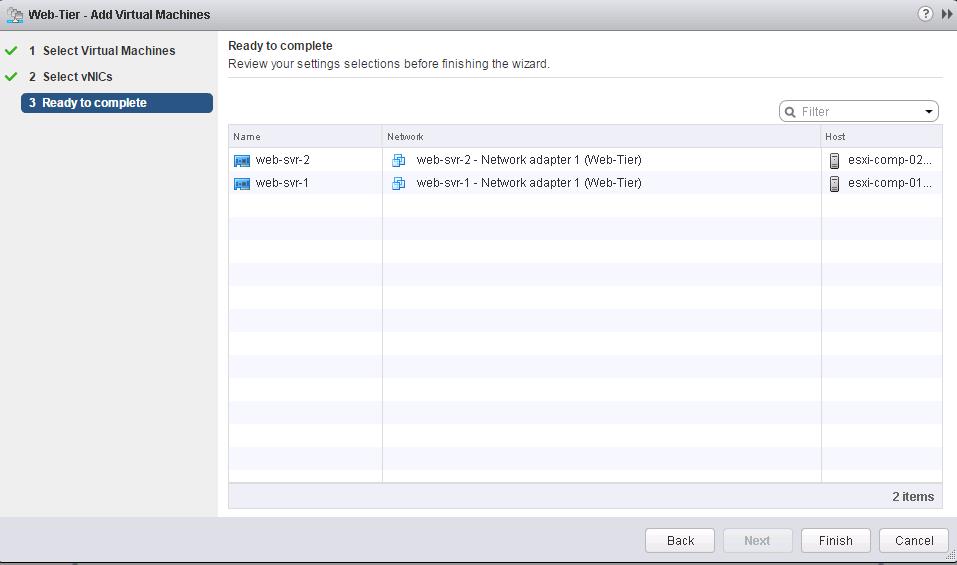
Review the Settings selected and Click Finish.
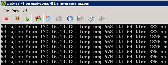
Simple Ping Test to prove the NSX Logical Switching:
Web-svr-1 – 172.168.10.11 (esxi-comp-01)
Web-svr-2 -172.16.10.12 (esxi-comp-02)
My ping to the VM “Web-svr-2” (172.16.10.12) from the VM “web-svr-1” (172.169.10.11) is a success and I am receiving the ICMP reply to the ping request. This both VM’s are running in different hosts/Clusters but still, my ping between the VM’s on the same logical switch is working well with the help of VXLAN.
When “web-svr-1” communicates to “web-svr-2”, it communicates over VXLAN transport network. When the VM communicates and the switch looks up the MAC address of Web-svr-2. the host is aware of its ARP/MAC/VTEP tables pushed to it by the NSX Controller where this VM resides. It is forwarded out to the VXLAN transport network. It is encapsulated within a VXLAN header and routed to the destination host based on the knowledge of the source host. Upon reaching the destination host the VXLAN header is stripped off and the preserved internal IP packet and frame continues to the host.
That’s it. We are done with Logical Switching. I hope you are clear with the concepts of NSX Logical Switch. We will discuss Distributed Logical routing in upcoming posts. I hope this is informative for you. Thanks for Reading!!!. Be Social and share it on social media, if you feel worth sharing it.
Other VMware NSX Related Posts:
VMware NSX Installation Part 1 – NSX Overview & Installation Prerequisites
VMware NSX Installation Part 2 – NSX Lab Design & Deploying NSX Manager
VMware NSX Installation Part 3 – Integrating NSX Manager with vCenter Server
VMware NSX Installation Part 4 – Deploying NSX Controller
VMware NSX Installation Part 5 – Checking NSX Controller Status
VMware NSX Installation Part 6 – Preparing Cluster and Hosts for NSX
VMware NSX Installation Part 7 – Verify NSX VIBs Installation from ESXi hosts
VMware NSX Installation Part 8 – Configuring VXLAN on the ESXi Hosts
VMware NSX Installation Part 9 -Create Segment ID and Transport Zones
VMware NSX Installation Part 11 – Creating Distributed Logical Router
VMware NSX – Backup & Restore VMware NSX Manager Data
VMware NSX – Unable to Delete/Remove Logical Switch
VMware NSX – How to Manually Install NSX VIBS on ESXi Host
VMware NSX – How to Manually Remove NSX VIBs from ESXi Host?
How to Remove NSX (Network & Security) Extension from vSphere Web Client


